PhaseLOG plus Panel |
  
|
PhaseLOG plus Panel |
|
Below, we have the information panel for the PhaseLOG plus.
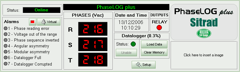
The upper left corner of the panel displays the device status indication.
Below the status information we can find the device alarm data. If an alarm is activated its indicator LED becomes yellow.
Beside the indications above mentioned you can see the device display image. It shows simultaneously the voltage for each of the three AC phases. The display can also indicate the device status. When “N/R” is displayed, that means the device selected is not responding. In this case the device status will indicate “Failed” or “Disconnected”. If the device status indicates “Maintenance”, the display exhibits only ‘- - -’.
Beside the display image we have the device internal date and time, followed by the output (relay) state indicator. A red indication means that output is turned ON.
Below the date/time and output state sections we can see the datalogger information. The first variable we can see is the datalogger internal memory usage (%). Below it the status indicates whether datalogger monitoring is turned ON or OFF and a button allows you to turn it ON or OFF. The other two buttons at the right allows you to Load the Data stored in the datalogger and Clear the Memory.
On the right side of the panel there is a model description and below it, an area for your company logo.
The panel includes the Setup button, to access the device functions. An access code is required.
See Also
URL of this page