Panel of PCT-1600 plus |
  
|
Panel of PCT-1600 plus |
|
The PCT-1600 plus panel is displayed as shown below.
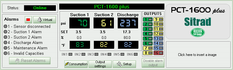
The upper left corner shows the device status.
Below the status section the panel shows the device alarm data. If an alarm is ON the corresponding indicator LED at left appears yellow. If an alarm occurs and the controller is configured for manual Reset, the Reset Alarm button becomes available so that a Reset can be made through the Sitrad.
In its middle section the panel shows the device digital displays. For each compressor the operating pressure, pressure setpoint, percentage of demand and temperature (when enabled) are displayed. The digital display can also exhibit the device status. “N/R” means the corresponding device is Not Responding. In this case the device status shows “Failure” or “Disconnected”. The digital display also shows “- - -“ when the device status is “Maintenance”.
Below the digital displays section we can see the status LEDs for the Digital Inputs. If the input is activated the corresponding indicator LED appears red. Positioning the mouse cursor over the input causes the system to display the actual input configuration.
At the right hand side of the digital display section we can find the device output status indicators. If an indicator appears in red this means that the corresponding output is activated. The outputs of each compressor are grouped by color. Green: Suction 1 – Yellow: Suction 2 – Blue: Discharge. If the output 16 is configured for alarm, it will appear in red and the Disable Alarm Output button becomes available allowing this output to be disabled manually.
The panel also contains the buttons Parameter, Output settings and Consumption. Consumption becomes available only when the energy consumption measurement is enabled through a digital input.
Click Setup to access the device functions. An access code is required.
Click Output settings to configure the capacity values, to set the device in maintenance mode and to view the output hour counter.
See Also
URL of this page