Painel of the MT-516 RVTi plus |
  
|
Painel of the MT-516 RVTi plus |
|
Below, we have the information panel for the MT-516 RVTi plus.
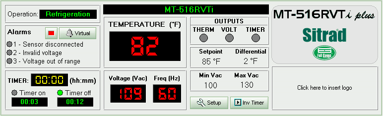
As we can see, the indication of the status of the instrument are in the upper left hand corner of the panel.
Below the indication of the status, we find the information referring to the alarms for the instrument. If any of them are activated, the indication light on the side of the alarm will turn yellow.
Right below the alarms, we have the indication of the internal timer for the instrument and right below that, the time that the timer for the instrument will be on and the time that it will be off, pursuant to what is configured in functions F09 and F10. The indication point for the respective label will be green, indicating the current state of the timer.
Next to the three items cited previously, is the representation of the instrument's display. It simultaneously shows the temperature of the sensor, the voltage of the network and the frequency thereof. The display may also indicate the status of the instrument, when the display shows "N/R", it will be indicating that the instrument in question is not responding. You can see that the status of the instrument is indicating "Failure" or "Disconnected". If the status of the instrument indicates "Maintenance", the display will simply show "- - -".
Beside of the representation of the display, we have the indicators of the state of the instrument outputs: THERM and TIMER. When a red light appears in the space corresponding to the output, this will indicate that it is on. The outputs activated indicate the following:
- THERM: the thermostat is on;
- TIMER: the timer is on.
Between the two representations of the outputs, we have the representation of the indicator VOLT.
Below the indication of the state of the outputs for the instrument, we can see the setpoint of the temperature, the control differential (hysteresis) and below that, the values of the minimum and maximum safety voltages.
On the right side of the panel we have a description of the model and, below that, the space for your company's logo.
Also on the panel, we have the buttons Setup e Inv Timer to access the functions of the instrument and invert the state of the timer respectively. It will be necessary to provide the access code for this purpose.
See Also
URL of this page