SwitchLOG plus Alarms |
  
|
SwitchLOG plus Alarms |
|
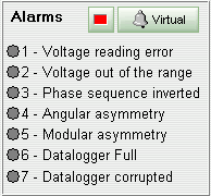
Alarm 1 indicate a measurement error on RS, ST or TR voltage value. Click on the text of the alarm to know in which phase the error occurred.
Alarm 2 indicates that some phase voltage is out of operation limits configured on Setup.
Alarm 3 indicates that phase sequence is reversed.
Alarm 4 indicates an angular asymmetry error and alarm 5 indicates a modular asymmetry error.
Alarm 6 indicates that internal device memory used by datalogger is full. In this case, load the data from device datalogger to SITRAD and clear the memory.
Alarm 7 indicates that datalogger memory contains corrupted samples. In this case, you should load the current data and then clean the memory.
See Also
URL of this page