Painel of the TC-940Ri plus |
  
|
Painel of the TC-940Ri plus |
|
Below, we have the information panel for the TC-940Ri plus
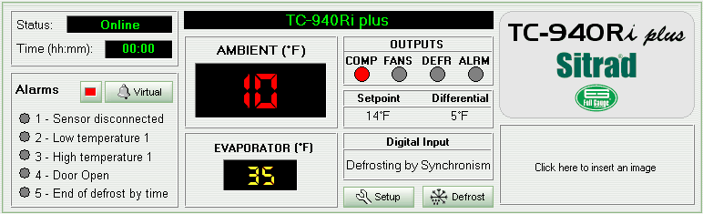
The upper left corner displays the device status and the amount of time it is performing the current function (frosting, defrosting, etc.)
Below the status data is the device alarm data. If any alarm is triggered the corresponding indicator at its left lights up in yellow.
Next to the status/alarm section is the device display section, which shows the temperature of both sensors, emphasizing the sensor 1 (room temperature).
The display shows primarily the sensors’ temperature, however it can also exhibit device status. When the display shows “N/R” the selected device is not responding. In this case the device status will be “Failure” or “Disconnected”. If device status is “Maintenance”, then “- - - “appears in the LED display.
Beside the LED display section are the device output indicators: COMP, FANS, DEFR and ALRM. When any indicator is red, the corresponding output is activated. The activated output operates as follows:
COMP: a frosting process is being performed;
FANS: the fans are turned ON;
DEFR: a defrosting process is being performed;
ALRM: the alarm output is activated.
Below the device output indicators is the set point (SETPOINT) and the hysteresis (HYSTERESIS) values. Below these values is the operation mode or the digital input status information.
At the right side of the panel is the model name and underneath a free space is available for the company logo.
Also the Setup and Defrost buttons are available on the panel to allow access to the device functions and to start the manual defrost (an access code is needed).
See Also
URL of this page