PCT-420Ri plus Panel |
  
|
PCT-420Ri plus Panel |
|
See below the PCT-420Ri plus data panel.
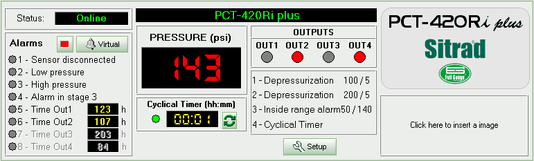
The device status indicator is found in the left upper corner of the panel.
The data related to device alarms can be read below the operation mode indicator. If an alarm is activated, the virtual LED beside the alarm becomes yellow.
Beside the indicators above mentioned you can see the device display showing the sensor pressure. The display can also show the device status. When “N/R” is displayed, means that the device selected is not responding. In this case the device status will indicate “Failed” or “Disconnected”. If the device status indicates “Maintenance”, only ‘- -’ will be displayed.
You can see the cyclic timer data below the display image. Starting from the left we have the current state (on/off) indicated. Follows the amount of time the cyclic timer is set in the current state and finally we have a button that switches the cyclic timer state between ON and OFF.
The state indicators for each device output are found beside the display image: OUT1, OUT2, OUT3 and OUT4. A red indication means that the output is activated. Below the output indicators we can find the operation mode description for each output. The setpoint and the hysteresis (or min./max. pressure if applicable) are found beside each description.
The Setup button accesses configuration for device functions. An access code is required.
See Also
URL of this page