Panel of MT-531Ri plus |
  
|
Panel of MT-531Ri plus |
|
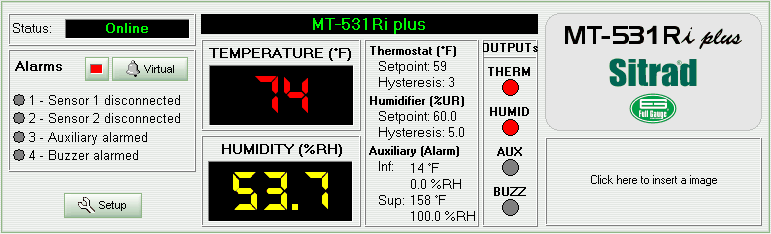
As we can notice, the device status is displayed in the panel upper left corner.
The device alarm data is displayed below the status display. The indicator LED beside the alarm appears yellow when the corresponding alarm is ON.
Nearby the alarm section is the device digital display showing the sensor temperature and humidity. The digital display also shows “N/R” when the corresponding device is Not Responding. In this case the device status shows “Fault” or “Disconnected”. The digital display also shows “- - -“ when the device status is “Maintenance”.
At the right side of the digital display we can see the controlling temperature (setpoint) and the hysteresis values configured for THERM (temperature controller), HUMID (humidity controller) and AUX (auxiliary) outputs. If AUX is configured for alarm, the corresponding upper and lower threshold values appear instead setpoint and hysteresis.
At the right side of the previous field we can see the status for each device output: THERM, HUMID, AUX and BUZZ. The indicator LED appears red when its corresponding output is ON. See below the meaning for each output turned ON.
- THERM: temperature controller turned ON
- HUMID: humidity controller turned ON
- AUX: auxiliary output turned ON
- BUZZ: alarm output turned ON.
In the right upper corner we can see the model name. Below the model name there is a free space where you can display your Company logo.
The lower left corner shows the Setup button. Click this button to access the device functions. An access code is required.
See Also
URL of this page